


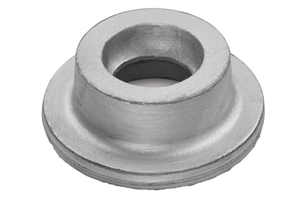
Stainless Steel Forged steel flanges are integral components used in piping systems to connect pipes, valves, pumps, and other equipment. They are created through a forging process that involves shaping and compressing heated metal into the desired flange shape. These flanges are crucial in providing a secure, leak-proof joint in various industries where high pressure, high temperature, and critical fluid handling are involved.
Forged steel flanges offer high strength, reliability, and resistance to corrosion, making them suitable for demanding environments where safety and performance are paramount in maintaining the efficiency of fluid handling systems.
| Size | ½" TO 54" |
|---|---|
| Pressure Rating | 150#, 300#, 600#, 900#, 1500#, 2500# |
| Standards | ASME B 16.5, ASME B 16.47, API 6A |
| Type | SORF, WNRF, SWRF, BLRF, Threaded etc. |
| Specials | Spacers, Spectacle Blinds, Drip Rings, RTJ, Tongue, Groove, Orifice, etc. |
| Stainless Steel Forged Face Flanges | |
| ASTM A182, A240 F 304, 304L, 304H, 316, 316Ti, 316H, 316L, 316LN, 309S, 309H, 310S, 310H,317, 317L, 321, 321H, 347, 347H, 201, 202, 904L | |
| Nominal Size and Bore J | Outside Dia. O | Minimum Flange Thickness Q | DIa. of Raised Face R | Minimum Wall Thickness | Dia. of Hub at Point of Welding H | Length Thru Hub Y | Drilling Template | Approx. Weight in Pounds | |||
| No. of Holes | Dia. of Holes | Dia. of Bolts | Dia. Bolt Circle | ||||||||
| 1/2 | 3.50 | 0.44 | 1.38 | 0.36 | 1.19 | 9 | 4 | 0.62 | 0.50 | 2.38 | 8 |
| 3/4 | 3.88 | 0.50 | 1.69 | 0.38 | 1.50 | 9 | 4 | 0.62 | 0.50 | 2.75 | 8 |
| 1 | 4.25 | 0.56 | 2.00 | 0.50 | 2.00 | 9 | 4 | 0.62 | 0.50 | 3.12 | 8 |
| 1 1/4 | 4.62 | 0.62 | 2.50 | 0.56 | 2.38 | 9 | 4 | 0.62 | 0.50 | 3.50 | 10 |
| 1 1/2 | 5.00 | 0.69 | 2.88 | 0.56 | 2.62 | 9 | 4 | 0.62 | 0.50 | 3.88 | 12 |
| 2 | 6.00 | 0.75 | 3.62 | 0.62 | 3.25 | 9 | 4 | 0.75 | 0.62 | 4.75 | 16 |
| 2 1/2 | 7.00 | 0.88 | 4.12 | 0.62 | 3.75 | 9 | 4 | 0.75 | 0.62 | 5.50 | 21 |
| 3 | 7.50 | 0.94 | 5.00 | 0.62 | 4.25 | 9 | 4 | 0.75 | 0.62 | 6.00 | 24 |
| 3 1/2 | 8.50 | 0.94 | 5.50 | 0.69 | 4.88 | 9 | 8 | 0.75 | 0.62 | 7.00 | 31 |
| 4 | 9.00 | 0.94 | 6.19 | 0.75 | 5.50 | 12 | 8 | 0.75 | 0.62 | 7.50 | 47 |
| 5 | 10.00 | 0.94 | 7.31 | 0.75 | 6.50 | 12 | 8 | 0.88 | 0.75 | 8.50 | 57 |
| 6 | 11.00 | 1.00 | 8.50 | 0.88 | 7.75 | 12 | 8 | 0.88 | 0.75 | 9.50 | 77 |
| 8 | 13.50 | 1.12 | 10.62 | 0.88 | 9.75 | 12 | 8 | 0.88 | 0.75 | 11.75 | 103 |
| 10 | 16.00 | 1.19 | 12.75 | 1.00 | 12.00 | 12 | 12 | 1.00 | 0.88 | 14.25 | 150 |
| 12 | 19.00 | 1.25 | 15.00 | 1.19 | 14.38 | 12 | 12 | 1.00 | 0.88 | 17.00 | 215 |
| 14 | 21.00 | 1.38 | 16.25 | 1.00 | 16.00 | 12 | 12 | 1.12 | 1.00 | 18.75 | 221 |
| 16 | 23.50 | 1.44 | 18.50 | 1.00 | 18.00 | 12 | 16 | 1.12 | 1.00 | 21.25 | 254 |
| 18 | 25.00 | 1.56 | 21.00 | 1.00 | 20.00 | 12 | 16 | 1.25 | 1.12 | 22.75 | 278 |
| 20 | 27.50 | 1.69 | 23.00 | 1.00 | 22.00 | 12 | 20 | 1.25 | 1.12 | 25.00 | 324 |
| 24 | 32.00 | 1.88 | 27.25 | 1.12 | 26.25 | 12 | 20 | 1.38 | 1.25 | 29.50 | 439 |
| Nominal Size and Bore J | Outside Dia. O | Minimum Flange Thickness Q | DIa. of Raised Face R | Minimum Wall Thickness | Dia. of Hub at Point of Welding H | Length Thru Hub Y | Drilling Template | Approx. Weight in Pounds | |||
| No. of Holes | Dia. of Holes | Dia. of Bolts | Dia. Bolt Circle | ||||||||
| 1/2 | 3.75 | 0.56 | 1.38 | 0.50 | 1.50 | 9 | 4 | 0.62 | 0.50 | 2.62 | 10 |
| 3/4 | 4.62 | 0.62 | 1.69 | 0.56 | 1.88 | 9 | 4 | 0.75 | 0.62 | 3.25 | 10 |
| 1 | 4.88 | 0.69 | 2.00 | 0.56 | 2.12 | 9 | 4 | 0.75 | 0.62 | 3.50 | 10 |
| 1 1/4 | 5.25 | 0.75 | 2.50 | 0.62 | 2.50 | 9 | 4 | 0.75 | 0.62 | 3.88 | 14 |
| 1 1/2 | 6.12 | 0.81 | 2.88 | 0.62 | 2.75 | 9 | 4 | 0.88 | 0.75 | 4.50 | 17 |
| 2 | 6.50 | 0.88 | 3.62 | 0.62 | 3.25 | 9 | 8 | 0.75 | 0.62 | 5.00 | 19 |
| 2 1/2 | 7.50 | 1.00 | 4.12 | 0.72 | 3.94 | 9 | 8 | 0.88 | 0.75 | 5.88 | 28 |
| 3 | 8.25 | 1.12 | 5.00 | 0.81 | 4.62 | 9 | 8 | 0.88 | 0.75 | 6.62 | 36 |
| 3 1/2 | 9.00 | 1.19 | 5.50 | 0.88 | 5.25 | 9 | 8 | 0.88 | 0.75 | 7.25 | 45 |
| 4 | 10.00 | 1.25 | 6.19 | 0.88 | 5.75 | 12 | 8 | 0.88 | 0.75 | 7.88 | 54 |
| 5 | 11.00 | 1.38 | 7.31 | 1.00 | 7.00 | 12 | 8 | 0.88 | 0.75 | 9.25 | 86 |
| 6 | 12.50 | 1.44 | 8.50 | 1.06 | 8.12 | 12 | 12 | 0.88 | 0.75 | 10.62 | 108 |
| 8 | 15.00 | 1.62 | 10.62 | 1.12 | 10.25 | 12 | 12 | 1.00 | 0.88 | 13.00 | 150 |
| 10 | 17.50 | 1.88 | 12.75 | 1.31 | 12.62 | 12 | 16 | 1.12 | 1.00 | 15.25 | 218 |
| 12 | 20.50 | 2.00 | 15.00 | 1.38 | 14.75 | 12 | 16 | 1.25 | 1.12 | 17.75 | 289 |
| 14 | 23.00 | 2.12 | 16.25 | 1.38 | 16.75 | 12 | 20 | 1.25 | 1.12 | 20.25 | 342 |
| 16 | 25.50 | 2.25 | 18.50 | 1.50 | 19.00 | 12 | 20 | 1.38 | 1.25 | 22.50 | 426 |
| 18 | 28.00 | 2.38 | 21.00 | 1.50 | 21.00 | 12 | 24 | 1.38 | 1.25 | 24.75 | 493 |
| 20 | 30.50 | 2.50 | 23.00 | 1.56 | 23.12 | 12 | 24 | 1.38 | 1.25 | 27.00 | 575 |
| 24 | 36.00 | 2.75 | 27.25 | 1.81 | 27.62 | 12 | 24 | 1.62 | 1.50 | 32.00 | 823 |
| Nominal Size and Bore J | Outside Dia. O | Minimum Flange Thickness Q | DIa. of Raised Face R | Minimum Wall Thickness | Dia. of Hub at Point of Welding H | Length Thru Hub Y | Drilling Template | Approx. Weight in Pounds | |||
| No. of Holes | Dia. of Holes | Dia. of Bolts | Dia. Bolt Circle | ||||||||
| 1/2 | 3.75 | 0.56 | 1.38 | 0.50 | 1.50 | 9 | 4 | 0.62 | 0.50 | 2.62 | 11 |
| 3/4 | 4.62 | 0.62 | 1.69 | 0.56 | 1.88 | 9 | 4 | 0.75 | 0.62 | 3.25 | 11 |
| 1 | 4.88 | 0.69 | 2.00 | 0.56 | 2.12 | 9 | 4 | 0.75 | 0.62 | 3.50 | 11 |
| 1 1/4 | 5.25 | 0.81 | 2.50 | 0.62 | 2.50 | 9 | 4 | 0.75 | 0.62 | 3.88 | 14 |
| 1 1/2 | 6.12 | 0.88 | 2.88 | 0.62 | 2.75 | 9 | 4 | 0.88 | 0.75 | 4.50 | 17 |
| 2 | 6.50 | 1.00 | 3.62 | 0.62 | 3.25 | 9 | 8 | 0.75 | 0.62 | 5.00 | 21 |
| 2 1/2 | 7.50 | 1.12 | 4.12 | 0.72 | 3.94 | 9 | 8 | 0.88 | 0.75 | 5.88 | 29 |
| 3 | 8.25 | 1.25 | 5.00 | 0.81 | 4.62 | 9 | 8 | 0.88 | 0.75 | 6.62 | 38 |
| 3 1/2 | 9.00 | 1.38 | 5.50 | 0.88 | 5.25 | 9 | 8 | 1.00 | 0.88 | 7.25 | 48 |
| 4 | 10.00 | 1.38 | 6.19 | 0.88 | 5.75 | 12 | 8 | 1.00 | 0.88 | 7.88 | 67 |
| 5 | 11.00 | 1.50 | 7.31 | 1.00 | 7.00 | 12 | 8 | 1.00 | 0.88 | 9.25 | 90 |
| 6 | 12.50 | 1.62 | 8.50 | 1.06 | 8.12 | 12 | 12 | 1.00 | 0.88 | 10.62 | 115 |
| 8 | 15.00 | 1.88 | 10.62 | 1.12 | 10.25 | 12 | 12 | 1.12 | 1.00 | 13.00 | 140 |
| 10 | 17.50 | 2.12 | 12.75 | 1.31 | 12.62 | 12 | 16 | 1.25 | 1.12 | 15.25 | 230 |
| Nominal Size and Bore J | Outside Dia. O | Minimum Flange Thickness Q | DIa. of Raised Face R | Minimum Wall Thickness | Dia. of Hub at Point of Welding H | Length Thru Hub Y | Drilling Template | Approx. Weight in Pounds | |||
| No. of Holes | Dia. of Holes | Dia. of Bolts | Dia. Bolt Circle | ||||||||
| 1/2 | 3.75 | 0.56 | 1.38 | 0.50 | 1.50 | 9 | 4 | 0.62 | 0.50 | 2.62 | 11 |
| 3/4 | 4.62 | 0.62 | 1.69 | 0.56 | 1.88 | 9 | 4 | 0.75 | 0.62 | 3.25 | 11 |
| 1 | 4.88 | 0.69 | 2.00 | 0.56 | 2.12 | 9 | 4 | 0.75 | 0.62 | 3.50 | 11 |
| 1 1/4 | 5.25 | 0.81 | 2.50 | 0.62 | 2.50 | 9 | 4 | 0.75 | 0.62 | 3.88 | 14 |
| 1 1/2 | 6.12 | 0.88 | 2.88 | 0.62 | 2.75 | 9 | 4 | 0.88 | 0.75 | 4.50 | 17 |
| 2 | 6.50 | 1.00 | 3.62 | 0.62 | 3.25 | 9 | 8 | 0.75 | 0.62 | 5.00 | 21 |
| 2 1/2 | 7.50 | 1.12 | 4.12 | 0.72 | 3.94 | 9 | 8 | 0.88 | 0.75 | 5.88 | 29 |
| 3 | 8.25 | 1.25 | 5.00 | 0.81 | 4.62 | 9 | 8 | 0.88 | 0.75 | 6.62 | 38 |
| 3 1/2 | 9.00 | 1.38 | 5.50 | 0.88 | 5.25 | 9 | 8 | 1.00 | 0.88 | 7.25 | 48 |
| 4 | 10.75 | 1.50 | 6.19 | 1.00 | 6.00 | 12 | 8 | 1.00 | 0.88 | 8.50 | 80 |
| 5 | 13.00 | 1.75 | 7.31 | 1.25 | 7.50 | 12 | 8 | 1.12 | 1.00 | 10.50 | 128 |
| 6 | 14.00 | 1.88 | 8.50 | 1.38 | 8.75 | 12 | 12 | 1.12 | 1.00 | 11.50 | 158 |
| 8 | 16.50 | 2.19 | 10.62 | 1.38 | 10.75 | 12 | 12 | 1.25 | 1.12 | 13.75 | 215 |
| 10 | 20.00 | 2.50 | 12.75 | 1.75 | 13.50 | 12 | 16 | 1.38 | 1.25 | 17.00 | 339 |
| Nominal Size and Bore J | Outside Dia. O | Minimum Flange Thickness Q | DIa. of Raised Face R | Minimum Wall Thickness | Dia. of Hub at Point of Welding H | Length Thru Hub Y | Drilling Template | Approx. Weight in Pounds | |||
| No. of Holes | Dia. of Holes | Dia. of Bolts | Dia. Bolt Circle | ||||||||
| 1/2 | 4.75 | 0.88 | 1.38 | 0.50 | 1.50 | 9 | 4 | 0.88 | 0.75 | 3.25 | 15 |
| 3/4 | 5.12 | 1.00 | 1.69 | 0.50 | 1.75 | 9 | 4 | 0.88 | 0.75 | 3.50 | 15 |
| 1 | 5.88 | 1.12 | 2.00 | 0.53 | 2.06 | 9 | 4 | 1.00 | 0.88 | 4.00 | 15 |
| 1 1/4 | 6.25 | 1.12 | 2.50 | 0.62 | 2.50 | 9 | 4 | 1.00 | 0.88 | 4.38 | 18 |
| 1 1/2 | 7.00 | 1.25 | 2.88 | 0.62 | 2.75 | 9 | 4 | 1.12 | 1.00 | 4.88 | 23 |
| 2 | 8.50 | 1.50 | 3.62 | 1.06 | 4.12 | 9 | 8 | 1.00 | 0.88 | 6.50 | 44 |
| 2 1/2 | 9.62 | 1.62 | 4.12 | 1.19 | 4.88 | 12 | 8 | 1.12 | 1.00 | 7.50 | 72 |
| 3 | 9.50 | 1.50 | 5.00 | 1.00 | 5.00 | 12 | 8 | 1.38 | 0.88 | 7.50 | 85 |
| 4 | 11.50 | 1.75 | 6.19 | 1.12 | 6.25 | 12 | 8 | 1.25 | 1.12 | 9.25 | 98 |
| 5 | 13.75 | 2.00 | 7.31 | 1.25 | 7.50 | 12 | 8 | 1.38 | 1.25 | 11.00 | 143 |
| 6 | 15.00 | 2.19 | 8.50 | 1.62 | 9.25 | 12 | 12 | 1.25 | 1.12 | 12.50 | 199 |
| 8 | 18.50 | 2.50 | 10.62 | 1.88 | 11.75 | 12 | 12 | 1.50 | 1.38 | 15.50 | 310 |
| 10 | 21.50 | 2.75 | 12.75 | 2.25 | 14.50 | 12 | 16 | 1.50 | 1.38 | 18.50 | 385 |
| Nominal Size and Bore J | Outside Dia. O | Minimum Flange Thickness Q | DIa. of Raised Face R | Minimum Wall Thickness | Dia. of Hub at Point of Welding H | Length Thru Hub Y | Drilling Template | Approx. Weight in Pounds | |||
| No. of Holes | Dia. of Holes | Dia. of Bolts | Dia. Bolt Circle | ||||||||
| 1/2 | 4.75 | 0.88 | 1.38 | 0.50 | 1.50 | 9 | 4 | 0.88 | 0.75 | 3.25 | 15 |
| 3/4 | 5.12 | 1.00 | 1.69 | 0.50 | 1.75 | 9 | 4 | 0.88 | 0.75 | 3.50 | 15 |
| 1 | 5.88 | 1.12 | 2.00 | 0.53 | 2.06 | 9 | 4 | 1.00 | 0.88 | 4.00 | 15 |
| 1 1/4 | 6.25 | 1.12 | 2.50 | 0.62 | 2.50 | 9 | 4 | 1.00 | 0.88 | 4.38 | 18 |
| 1 1/2 | 7.00 | 1.25 | 2.88 | 0.62 | 2.75 | 9 | 4 | 1.12 | 1.00 | 4.88 | 23 |
| 2 | 8.50 | 1.50 | 3.62 | 1.06 | 4.12 | 9 | 8 | 1.00 | 0.88 | 6.50 | 44 |
| 2 1/2 | 9.62 | 1.62 | 4.12 | 1.19 | 4.88 | 12 | 8 | 1.12 | 1.00 | 7.50 | 72 |
| 3 | 10.50 | 1.88 | 5.00 | 1.12 | 5.25 | 12 | 8 | 1.25 | 1.12 | 8.00 | 84 |
| 4 | 12.25 | 2.12 | 6.19 | 1.19 | 6.38 | 12 | 8 | 1.38 | 1.25 | 9.50 | 118 |
| 5 | 14.75 | 2.88 | 7.31 | 1.38 | 7.75 | 12 | 8 | 1.62 | 1.50 | 11.50 | 195 |
| 6 | 15.50 | 3.25 | 8.50 | 1.50 | 9.00 | 12 | 12 | 1.50 | 1.38 | 12.50 | 235 |
| 8 | 19.00 | 3.62 | 10.62 | 1.75 | 11.50 | 12 | 12 | 1.75 | 1.62 | 15.50 | 366 |
| 10 | 23.00 | 4.25 | 12.75 | 2.25 | 14.50 | 12 | 12 | 2.00 | 1.88 | 19.00 | 610 |
| Nominal Size and Bore J | Outside Dia. O | Minimum Flange Thickness Q | DIa. of Raised Face R | Minimum Wall Thickness | Dia. of Hub at Point of Welding H | Length Thru Hub Y | Drilling Template | Approx. Weight in Pounds | |||
| No. of Holes | Dia. of Holes | Dia. of Bolts | Dia. Bolt Circle | ||||||||
| 1/2 | 5.25 | 1.19 | 1.38 | 0.61 | 1.69 | 9 | 4 | 0.88 | 0.75 | 3.50 | 18 |
| 3/4 | 5.50 | 1.25 | 1.69 | 0.62 | 2.00 | 9 | 4 | 0.88 | 0.75 | 3.75 | 18 |
| 1 | 6.25 | 1.38 | 2.00 | 0.62 | 2.25 | 9 | 4 | 1.00 | 0.88 | 4.25 | 18 |
| 1 1/4 | 7.25 | 1.50 | 2.50 | 0.81 | 2.88 | 9 | 4 | 1.12 | 1.00 | 5.12 | 27 |
| 1 1/2 | 8.00 | 1.75 | 2.88 | 0.81 | 3.12 | 9 | 4 | 1.25 | 1.12 | 5.75 | 33 |
| 2 | 9.25 | 2.00 | 3.62 | 0.88 | 3.75 | 9 | 8 | 1.12 | 1.00 | 6.75 | 48 |
| 2 1/2 | 10.50 | 2.25 | 4.12 | 1.00 | 4.50 | 9 | 8 | 1.25 | 1.12 | 7.75 | 66 |
| 3 | 12.00 | 2.62 | 5.00 | 1.12 | 5.25 | 9 | 8 | 1.38 | 1.25 | 9.00 | 97 |
| 4 | 14.00 | 3.00 | 6.19 | 1.25 | 6.50 | 12 | 8 | 1.62 | 1.50 | 10.75 | 159 |
| 5 | 16.50 | 3.62 | 7.31 | 1.50 | 8.00 | 12 | 8 | 1.88 | 1.75 | 12.75 | 248 |
| 6 | 19.00 | 4.25 | 8.50 | 1.62 | 9.25 | 12 | 8 | 2.12 | 2.00 | 14.50 | 358 |
| 8 | 21.75 | 5.00 | 10.62 | 2.00 | 12.00 | 16 | 12 | 2.12 | 2.00 | 17.25 | 589 |
| 10 | 26.50 | 6.50 | 12.75 | 2.38 | 14.75 | 16 | 12 | 2.62 | 2.50 | 21.25 | 997 |
| Off-Shore Oil Drilling Companies | Power Generation | Petrochemicals | Gas Processing |
| Specialty Chemicals | Pharmaceuticals | Pharmaceutical Equipment | Chemical Equipment |
| Sea Water Equipment | Heat Exchangers | Condensers | Pulp & Paper Industry |